Infall / Inside the build
Where does the light go?
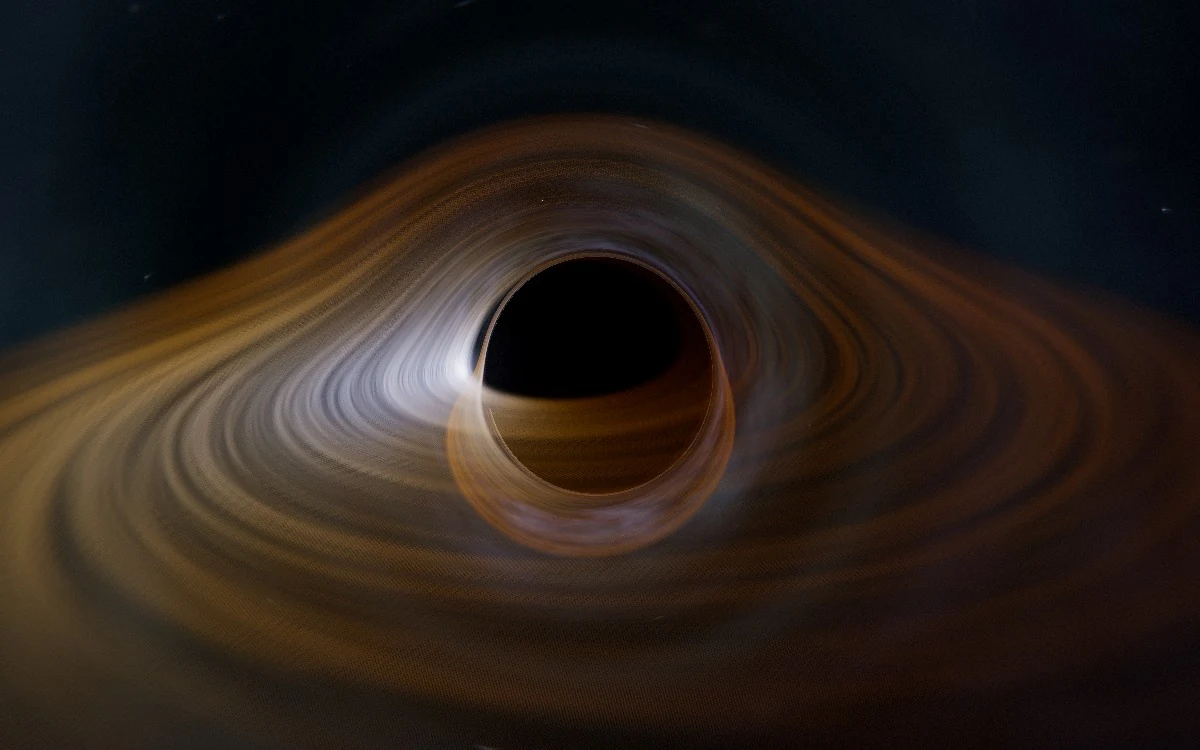
The bright arc above a black hole can come from gas on the far side. Follow one frame of Infall, from a scroll gesture to curved light paths and the final pixels in your browser.
On this page
System trace
Follow a frame through the renderer
Scroll controller
The browser maps the current scroll position to progress along the descent. Each frame moves toward that target.
- Read the scroll · Scroll controller
The browser maps the current scroll position to progress along the descent. Each frame moves toward that target. Progress from zero to one
- Place the camera · Three.js scene
The authored path converts progress into a camera pose and field of view. Logarithmic distance changes give the last part of the approach room on screen. At 58% progress · eight Schwarzschild radii
- Trace the light · GLSL raymarcher
Each sample follows a curved ray and gathers light where it crosses gas. An escaping ray also samples the distant sky in its final direction. Captured ray · previously gathered disk light only
- Resolve the image · Temporal compositor
Two alternating buffers mix the new result with history. Motion reduces the contribution of older samples before the finishing passes. History weight falls as camera movement increases
Why the far side of the disk is visible
Partway through Infall’s descent, the glowing disk around the black hole appears to fold up behind it. Follow the bright arc over the top. Some of the light in that arc started on the far side of the disk. Gravity bent its path enough for it to reach the camera. Turn the camera and that same piece of gas can appear somewhere else in the frame. That relationship between where light starts and where it arrives is the reason to render the scene live. See the disk and photon-ring frames.
The starting point is GW231123, a merger detected through gravitational waves in November 2023. The observations constrain the masses and spins of the objects involved. Infall takes a representative remnant spin and imagines a trip through its surroundings. The path light takes is calculated from a model of rotating spacetime. The gas, stars and camera choreography supply a scene through which to see that calculation. LIGO’s event summary.
From a scroll gesture to a camera position
A flick on the trackpad gives the program a destination. A passive scroll listener divides the distance down the page by the available scrolling distance and clamps the result between zero and one. On each animation frame, the scroll engine moves toward that target using the elapsed time. With reduced motion enabled, it takes the target immediately. Caching the page height keeps a layout measurement out of this loop.
The scene translates that number into a camera pose. At 58 percent progress, for example, the authored path puts the camera eight Schwarzschild radii from the center. A Schwarzschild radius is the length scale associated with the black hole’s mass. Between the chosen positions, the camera eases its angle and interpolates distance logarithmically. This gives the reader room to explore both the wide approach and the final few radii. The instrument panel reads the resulting radius and clock-rate factor from the scene. It accumulates elapsed time every frame and updates the visible readouts every fourth frame.
The camera, the instruments and the GPU share a small contract. TypeScript evaluates the pose and the rotating-hole geometry on the CPU. It sends radius, inclination, field of view, spin and horizon radius to the GPU as uniforms, values common to all samples in that draw. The HUD consumes the radius and clock-rate factor from the same scene object. Reading one pixel back from the GPU to update a clock would introduce a wait for earlier drawing to finish. Sharing the CPU state avoids that round trip.
Architecture diagram
One frame, two kinds of memory
The CPU holds the camera and geometry. The GPU follows light paths and retains color from earlier frames. The HUD can read the shared scene state independently of the image.
Trace a ray. Scroll progress selects a pose. Camera and Kerr parameters cross to the GPU as uniforms. Each ray integrates position, momentum and disk emission. Its color lands in the current-frame texture.
Resolve a frame. The accumulator reads the current texture and the previous history, writing a new history target. The compositor upscales that result, adds bloom and grading, then presents it. The targets exchange roles for the following frame.
Three frames from the same renderer
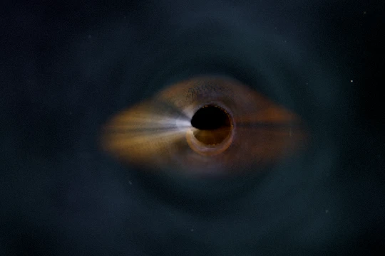 16% · 33 radii
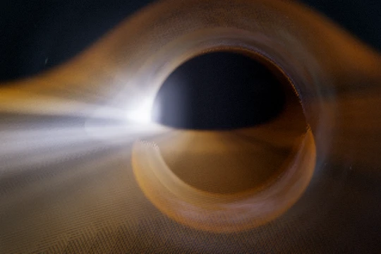 58% · 8 radii
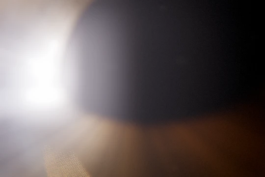 93% · 3.3 radii
For this check I set the canvas to 540 by 360 and requested 68,000 physics samples per frame. The engine allocated a 319 by 213 ray buffer. The canvas has 194,400 pixels. The expensive pass drew 67,947 samples before any extra rays near the rim, about 35% of the display pixel count. The compositor still had the full canvas for the finishing passes. Reduced motion kept the temporal-history weight at zero in these captures. These are buffer dimensions recorded in a software-rendered check.
What one pixel has to decide
Three.js sends a rectangle covering the view to the graphics processor. For each sample on that rectangle, a small GLSL program starts a ray at the camera and works backward. It tracks the ray’s position and momentum through the Kerr model of a spinning black hole. The calculation uses shorter steps near the disk and the photon ring, where a small change of direction can separate a ray that escapes from one that falls in.
The ray carries two vectors, position and momentum. A Cartesian Kerr–Schild coordinate system keeps both well behaved along the spin axis. That choice has a visible consequence. In a coordinate system with a singularity at the pole, neighboring rays can spend different amounts of their limited step budget crossing the same narrow part of the picture. The result can be a seam above the hole. Here, each step evaluates the direction and momentum change at the start, evaluates them again at the predicted midpoint, and advances using the midpoint values. Long steps in the far field save work for the thin disk and the sharply curved paths near the hole.
Along the way, the ray collects light from the gas it crosses. A ray captured near the horizon can still carry disk light encountered earlier. A ray that escapes adds the distant sky from its final direction. That last detail explains how a star can appear in an unexpected part of the sky. The visible disk filaments come from procedural noise, while the color treatment gives approaching gas a brighter, cooler appearance. The model determines where the ray went. The art direction determines what was there to see.
Four possible endings give the renderer different colors even for rays that start almost side by side.
| End of the ray | What the shader knows | How it finishes the sample |
|---|---|---|
| Near the horizon | Radius is within 0.02 model units of the outer horizon | Keep previously collected light and suppress the distant background. |
| Escaped | Radius exceeds 44 units and the ray points outward | Sample the sky in the final direction, scaled by the fraction of light still getting through the gas. |
| Opaque gas | The remaining transmission drops below 0.004 while integrating the disk | Stop accumulating. Light behind this material would contribute very little. |
| Step budget spent | The numerical path has reached neither boundary | Estimate the background contribution from the last radius. A ray still close to the hole can look darker. |
Where the renderer spends its next millisecond
The edge of the shadow is expensive. Two nearby samples can follow very different paths, and under-sampling makes the rim sparkle. The renderer can afford extra rays in a narrow band around the silhouette while giving quieter regions fewer samples. When frames slow down, it can reduce integration steps and extra rays. Under sustained pressure at its cheapest tier it can also shrink the buffer used for physics. The final image has a separate resolution budget, so the expensive light calculation and finishing effects can run at different densities.
The renderer also borrows samples from earlier frames. Two image buffers alternate roles so the current result can be blended with the previous history. A steady view can recover fine detail over time. Swing the camera and those old samples describe a different arc of the disk. The renderer measures camera movement, reduces the weight of that history and lets the new silhouette resolve. Upscaling, bloom and color grading follow the blend.
What survives from one frame to the next
The ray pass writes its freshly computed color into a half-float texture. A second pass reads that texture and last frame’s accumulated texture, then writes their weighted mixture into a different target. Only after the compositor has read the new target do the history buffers exchange roles. Reading from and drawing into the same texture in one pass would make the result depend on pixels currently being written.
In a settled view the history weight can reach 0.95. If the old value of one color channel is 0.20 and the new sample is 0.80, the next accumulated value is only 0.23. A solitary bright sample barely disturbs the disk. A moved silhouette at that blend weight would leave a trail. The renderer measures changes in camera radius, inclination and yaw as well as scroll speed. During fast motion it reduces the blend and can freeze the jitter pattern. A resize restarts the settling period because the old grid no longer lines up with the new one. The final passes reconstruct the image using Catmull–Rom filtering, then apply bloom, grading and output conversion.
The controller can first lower its step count and the number of extra samples around the silhouette by changing uniforms. These changes preserve the textures. Only after continued slow frames at the cheapest tier does it reduce the physics pixel budget, which resizes the targets and costs accumulated detail. Recovery waits for sustained headroom. That asymmetry keeps a single fast frame from triggering a costly resize in the middle of a slow passage.
A test the shadow can answer
I would test the shadow boundary before tuning the glow. In orbit mode, the page can draw a predicted rim from equations for the photon orbits. The raymarcher reaches the same boundary by taking numerical steps. These two paths offer a cross-check. Set the spin to zero, where the predicted outline is circular, then repeat with the guided descent’s spin of 0.84 at the same camera angle. Explore orbit mode.
The geometry function provides a cheap first check. In the renderer’s units the zero-spin case returned a horizon radius of 1, an innermost stable circular orbit of 3, and equal prograde and retrograde photon-orbit radii of 1.5. At spin 0.84 the same function returned 0.7713, 1.3447, and 0.8592 / 1.9278 respectively. The two photon orbits separate when spin matters. These values test the scene’s model inputs. A shader could still draw the wrong outline with all four numbers correct.
A regression test could freeze the camera and shader clock, record the boundary where rays switch between capture and escape, then measure its displacement from the predicted rim at two quality tiers. This targets a real failure mode. A ray that exhausts its step budget while still close to the hole receives a dimmed sky contribution. Too many unfinished rays can darken the image even when the frame arrives on time. Recording both the edge displacement and the frame interval would show whether a speed improvement preserves the feature the reader came to see.
Review notes
Corey Crooks built Infall. This walkthrough draws on the product and its implementation.
- The scroll controller, camera path, ray integration shader and temporal compositor establish the path of a frame.
- The local production JavaScript bundle matched the bundle served by Infall. The public build notes and LIGO event summary give the visual and observational context.
- Rendered three fixed camera positions in the local application with headless Chromium and its software WebGL renderer. Calculated the reference radii with the implementation’s kerrGeometry function.
The proposed shadow-boundary test is a way to measure visual error. This review includes no device frame-rate benchmarks.